Couplings
Locomotive & Carriage Screw Link Couplings
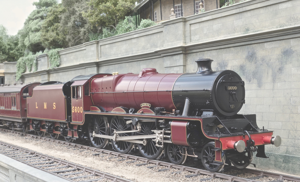
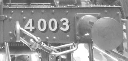
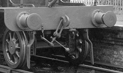
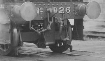
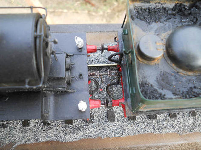
These are an important feature, especially at the front, so good attention to detail here will certainly benefit a quality model.
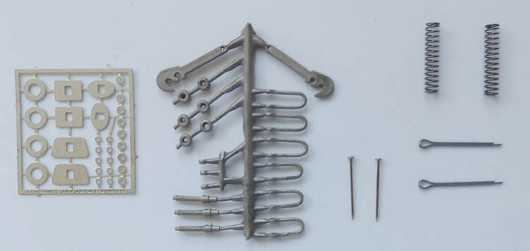
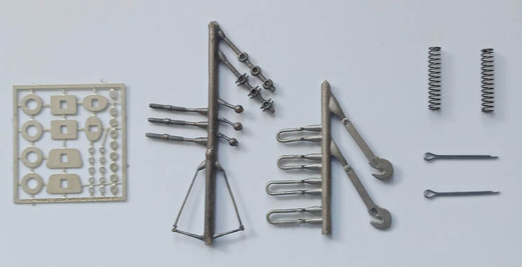
These 7mm scale CPL kits all come with brass lost wax cast hooks and shackles to give the correct prototypical appearance.
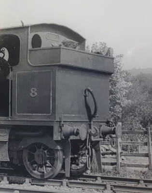
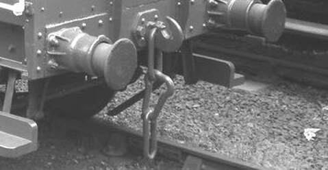
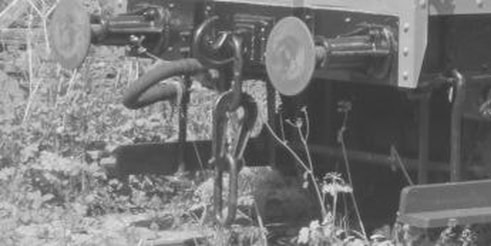
We do suggest a careful inspection of a period photograph of the vehicle you are modelling to ensure historical accuracy. While the couplings listed below are very well researched and reproduced, many vehicles were modified with different types of couplings during their service lives.
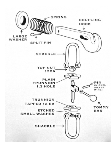
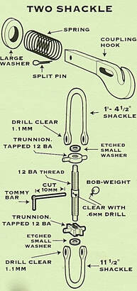
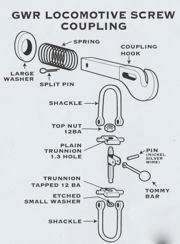
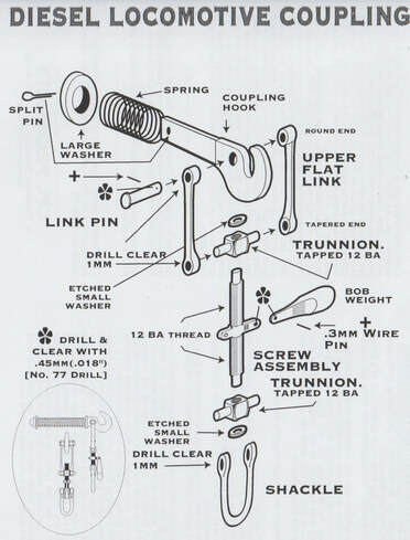
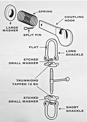
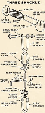
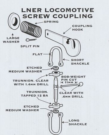
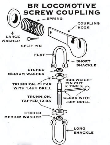
An exploded drawing and a written assembly sequence fold out of the pack, with useful tips and a build sequence, and these are also included at the bottom of this page, so by all means have a quick read through to see what's involved in making a CPL kit.
|
SR Locomotive Screw Couplings
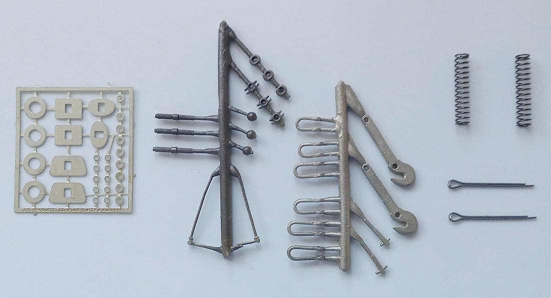
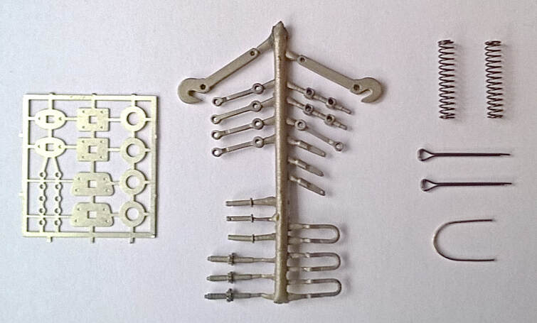
Three shackle couplings
Please quote CPL 29 £11.10 |
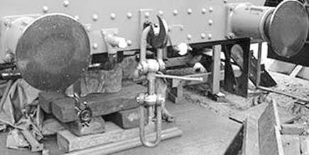
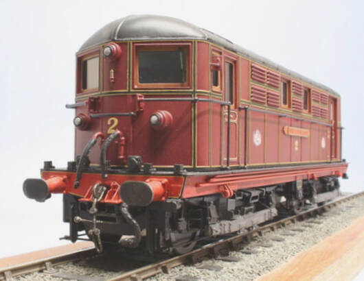
This style was fitted to all new construction commencing with the 'Q' class and the subsequent 'Q1', MN, and 'WC/BB' classes. Photographs confirm that this configuration was in use by 1937 and was progressively fitted to all extant SECR and SR locomotives by the mid-1940's. Ex LBSCR 'K' and 'C3' also received this style of coupling, possibly other, but not all, Brighton classes as well. From 'known' records they were not fitted to any ex LSWR loco's. The kit contains enough parts for two complete sprung couplings and hooks....
|
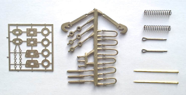
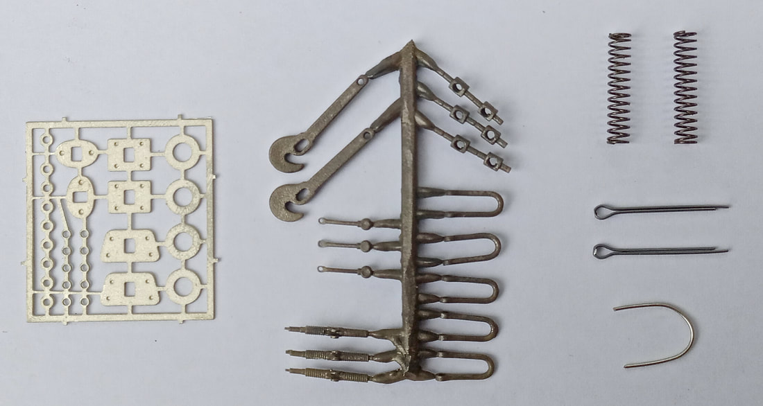
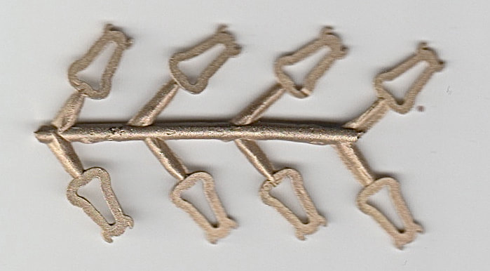
Buffer Beam Safety Chains
Please quote CPL 42 £9.60
Please quote CPL 42 £9.60
|
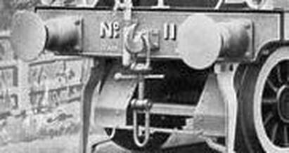
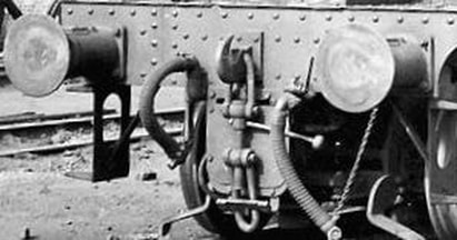
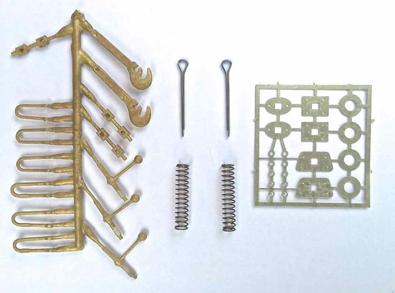
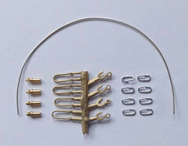
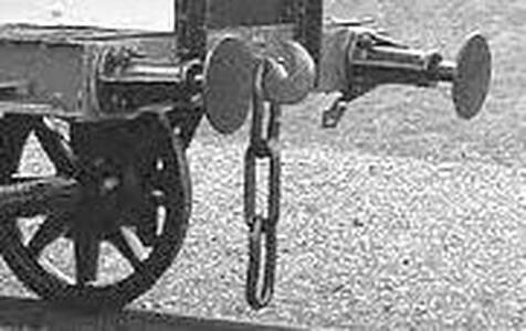
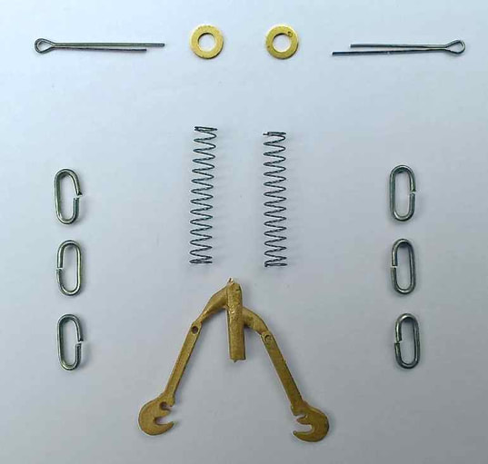
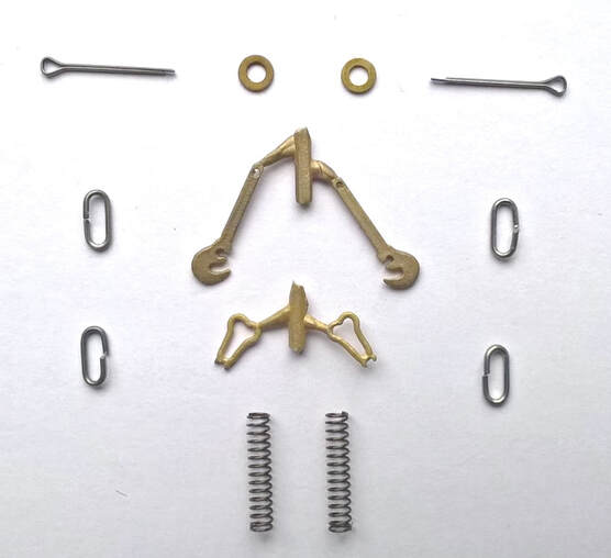
This is a recently developed kit for pre-grouping safety chains. They were used on locomotives as well as seeing some carriage and wagon use. Of course, these did vary from company to company, so we have tried to include enough parts and spare components to enable different variations to be made quite easily. The components illustrated opposite, the kit I have included some copy from the instruction leaflet and a simple exploded view, please see below.
|
Pre Grouping and Industrial Couplings
Screw Coupling Instructions
To help you achieve the best results the following tools can be put to good use for assembling the kit:
A piercing saw with a fine blade
No. 73 drill (0.6mm), in a pin chuck
No. 65 drill (0.9mm), in a pin chuck
No. 54 drill (1.4mm), in a pin chuck
A pair of long nose pliers
A set of small fine files,
Some very fine Emery board.
Brass parts can be chemically blackened with Carr’s Metal Black if required.
These kits produce a fine looking scale adjustable coupling, and are an important focal point at the front of an engine. Some careful workmanship will help to make it an authentic feature.
The No 65 drill (.9mm) is for holes through shackles and through the coupling hook for the split pin.
The No. 54 (1.4mm) is for the hole through the top trunnion on Locomotive coupling.
The No. 73 (6mm) for hole through bob weight and coupling screw (Loco) and 12BA taper tap. A pin chuck, Fine files and very fine Emery boards.
Eileen's Emporium can usually supply most of the above.
Clean up the castings using fine files and emery sticks where necessary. A lot of this is best done whilst the castings are still attached to the sprue. Run a No. 65 (.9mm) drill in a pin chuck down the line of shackle links to clear out holes.
A 12BA tap may be required to clean out the tapped holes in the bottom trunnion. The trunnions for the Loco couplings are mounted in pairs on the sprue. The inner one can be cleaned out with a No. 54 (1.4mm) drill. Hold in a small vice or pliers to be safe. It is best to remove the components as required with a fine piercing saw, as side cutters or snips can deform the ends of some parts and make it difficult to fit retaining washers etc.
Take care not to cut the screwed main portion of the coupling screw too short. There should be a short section of reducted diameter on the end of the screw, onto which is fitted an etched retaining washers AFTER the trunnion(s) has been fitted on.
On the main screwed part the top trunnion is placed on top above the hole for the bob weight and a paper washer placed over it. The top washer is soldered on to retain the 'free moving trunnion The paper washer serves two purposes. It gives a working clearance and also prevents solder running into the joint and may now be pulled out.
Next solder the bottom retaining washer with the trunnion screwed up so that is not fixed by the solder.
Clear the hole in the bob-weight and the cross hole in the main screwed portion with a .6mm drill. The next stage is to cut the pin supplied to 11mm long, put through the hole in the main body and solder on the bob-weight on the end.
Before cutting the pin it is suggested that the pin head is reduced in diameter slightly and flattened with a small file.
Saw the shackles from the sprue and clean up the sawn ends with fine file and emery. Check the holes in the ends will fit over the trunnion pegs. Open out the holes as necessary with a taper broach or the end of a fine rat tail needle file, so that they are a nice easy fit. Spread the end of the shackle sufficiently so that the end will fit over the trunnion pegs and close them, with care, by finger pressure. If necessary give them a GENTLE squeeze with a pair of pliers to close them up. Make sure they work freely and there are no tight spots.
The top shackle is fitted to the hook as in prototype practice. The flat on the short shackle is dropped into a slot in the draw hook and rotated so that the curved part of the shackle sits in the hole.
Generally make sure that all the joints work freely and that there is no stiffness so that the couplings hangs naturally.
Assemble the coupling through the buffer beam and place the spring and large etched washer over the end and secure with a splitpin.
As there is no standards to what size the hole is in a buffer beam in many kits, there are some etched plates included to stop the hook going too far into the buffer beam.
Shackle & Chain Instructions
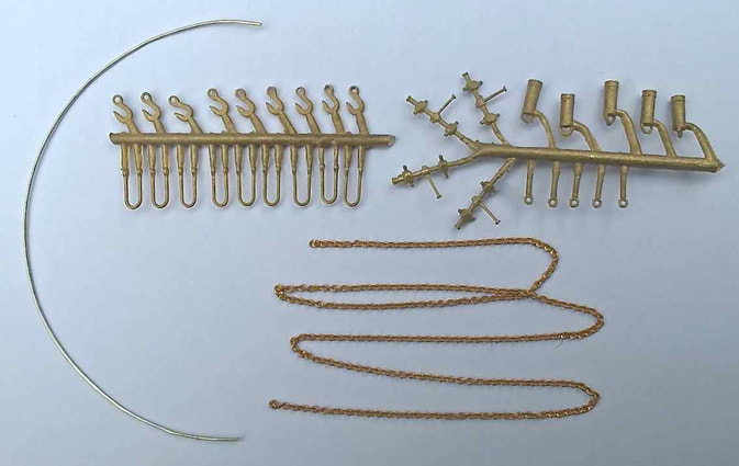
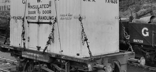
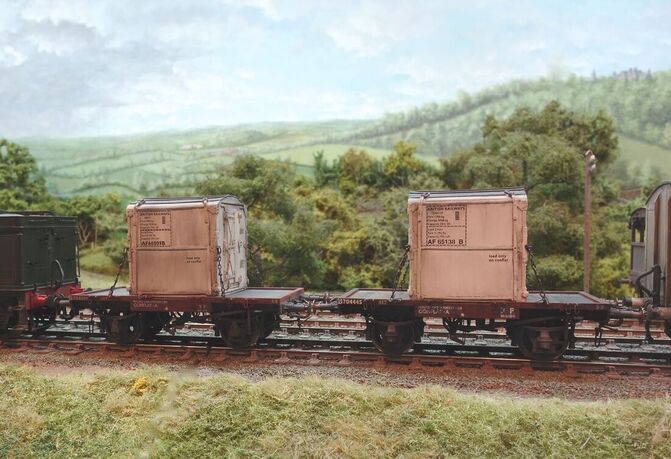
These components may be used to make a representation of the chins to secure containers to Conflat wagons. Enough components are included to enable four securing chains to be made - four - are required for each container. Whilst they have been designed primarily for use in conjunction with the Parkside Dundas GWR Container Wagon (Diagram H7) and Container they may also be used on models of other company's vehicles - the LNER in particular used very similar securing chains on its Conflat wagons.
The shackles are also very similar to those used on bolster wagons and may be used with a longer length of chain for securing loads of timber, girders, etc.
Only simple tools are required for assembly of the securing chains: fine side cutters, tapered broach, a piercing saw with fine blades, 1mm and 1.6mm drills, pin chuck, fine files and emery boards, fine nose pliers and tweezers. Assembly of the securing chains is not difficult and once the first has been assembled and the method established, the remaining chains will be much quicker.
Start by preparing the components. The castings should be cleaned up using the fine files and emery boards. Much of this is best done whilst the castings are still attached to the sprue. Using the 1mm spring cylinders are supplied but only four per container are needed. Components may be removed from the sprue using the side cutters and finally cleaned up using the fine files and emery boards. You may prefer to cut the parts from the sprue using the piercing saw which will reduce the possibility of deforming the components before they are similarly cleaned up.
The length of supplied copper wire should be wound round the 1.6mm drill to form a sort of tightly wound coil spring. This should be held firmly and using the piercing saw and cutting along the length of the drill a series of circular links are formed. Two of these are required for each securing chain - eight per container.
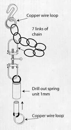
Assembly starts with the central tightening screw. A shackle link is taken and the holes are opened with the tapered broach to be an easy fit over the pegs on the tightening screw casting. The spring cylinder is slid onto the link and the ends of the shackle are spread so that they will fit over the pegs. The links may be closed over the pegs using finger pressure and any fine adjustment should be made using the fine nosed pliers. Similarly the top shackle link may be prepared and a length of chain is supplied chain is also required. The chain should be seven links in length and the top shackle link is fed through the end link and again through the sixth link thus forming a small loop. Using the fine nosed pliers the gap in one of the prepared wire loops is opened up. The end link of the length of chain and one of the hooks are slipped onto the loop before the gap is closed again trapping them in place. The ends of the top shackle link are closed over the pegs of the tightening screw casting.
A small cast eye is removed from the sprue and another of the copper wire loops is fitted to it using the fine nosed pliers.
At this point there should be two sub assemblies: 1) the securing chain consisting of hook, length of chain, shackle and spring cylinder and 2) the small eye which fits into the spring cylinder with the loop attached. It is advisable to chemically blacken the chains and this is best done now before they are fitted to the wagon.
Fitting is easily done. The hook is attached to the corner pillar ring on the container with the hook facing outwards in accordance with the official instructions whilst the loop of the eye is slipped over the side hook on the wagon. The spindle of the eye is then glued into the end of the spring cylinder so as to make the securing chain taut between the two fixing points. Then repeat another three times!
It is not recommended that these chains be used to secure the container to the wagon. The container is best fixed securely to the floor of the wagon and the securing chains added for cosmetic purposes. If the components are being used on the Parkside Dundas kit it is also recommended that the plastic side hooks are replaced with new brass wire hooks for additional strength and durability.
Wagon Coupling Instructions
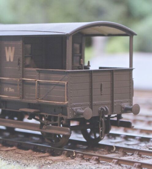
These Wagon Couplings are supplied with Brass Lost Wax coupling hooks and instanter parts to give a better, more substantial appearance to the coupling.
To help you to achieve this the following tools should be to hand for assembly: A piercing saw with a fine blade, drill No. 65 (.9mm). A pin chuck, small fine files and very fine emery boards.
Eileen's Emporium can usually supply most of the above.
To help you to achieve this the following tools should be to hand for assembly: A piercing saw with a fine blade, drill No. 65 (.9mm). A pin chuck, small fine files and very fine emery boards.
Eileen's Emporium can usually supply most of the above.
Separate the hooks and instanter parts from the sprue, clean up the castings using fine files and emery boards where necessary. Run and No. 65 (.9mm) drill in a pin chuck through the hole for the split pin and assemble, splitting the links (as necessary) to attach to each other and realigning as the illustration according to the type of the coupling you have acquired.
The brass parts can be chemically blackened with Carr's Metal Black if required.
The brass parts can be chemically blackened with Carr's Metal Black if required.

